Inspection technology
Optical inspection of surface finishes
By automating the inspection, we eliminate the human error factor and thus increase the quality of the inspection. Our systems are based on a defined quality standard, whereby any deviation is reliably identified. With highly developed 3D surface inspections and precise dimensional checks, we guarantee an exact analysis of your components. Our systems also enable systematic defect classification and precise counting of components to ensure seamless quality analysis and documentation. This allows us to increase the efficiency of your inspection processes while reducing the time required for quality control.
The principle of surface inspection
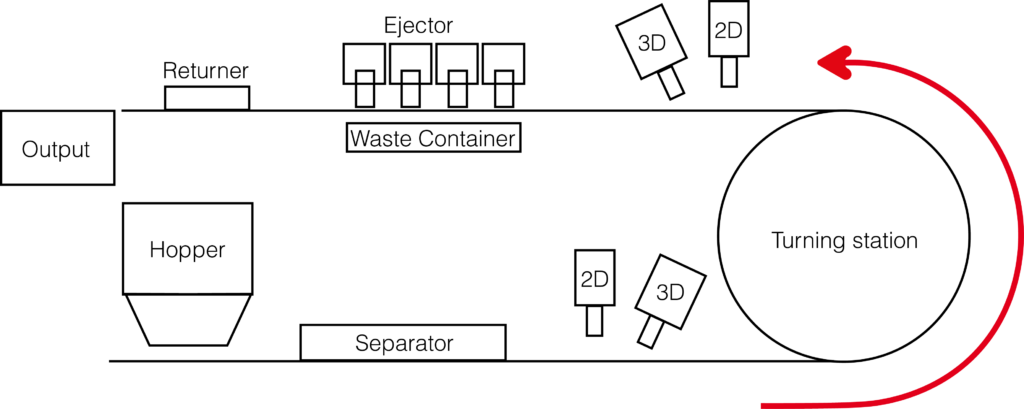
From handling and image acquisition to the final decision: our inspection systems inspect your workpiece surfaces in the blink of an eye – reliably, reproducibly and perfectly integrated into existing production processes.
Inspection Technology
Lorem ipsum dolor sit amet, consectetur adipiscing elit. Ut elit tellus, luctus nec ullamcorper mattis, pulvinar dapibus leo.
Tools
The right tool for your application
In addition to surface inspection and dimensional control, further sensors can be integrated into the system concepts if required.
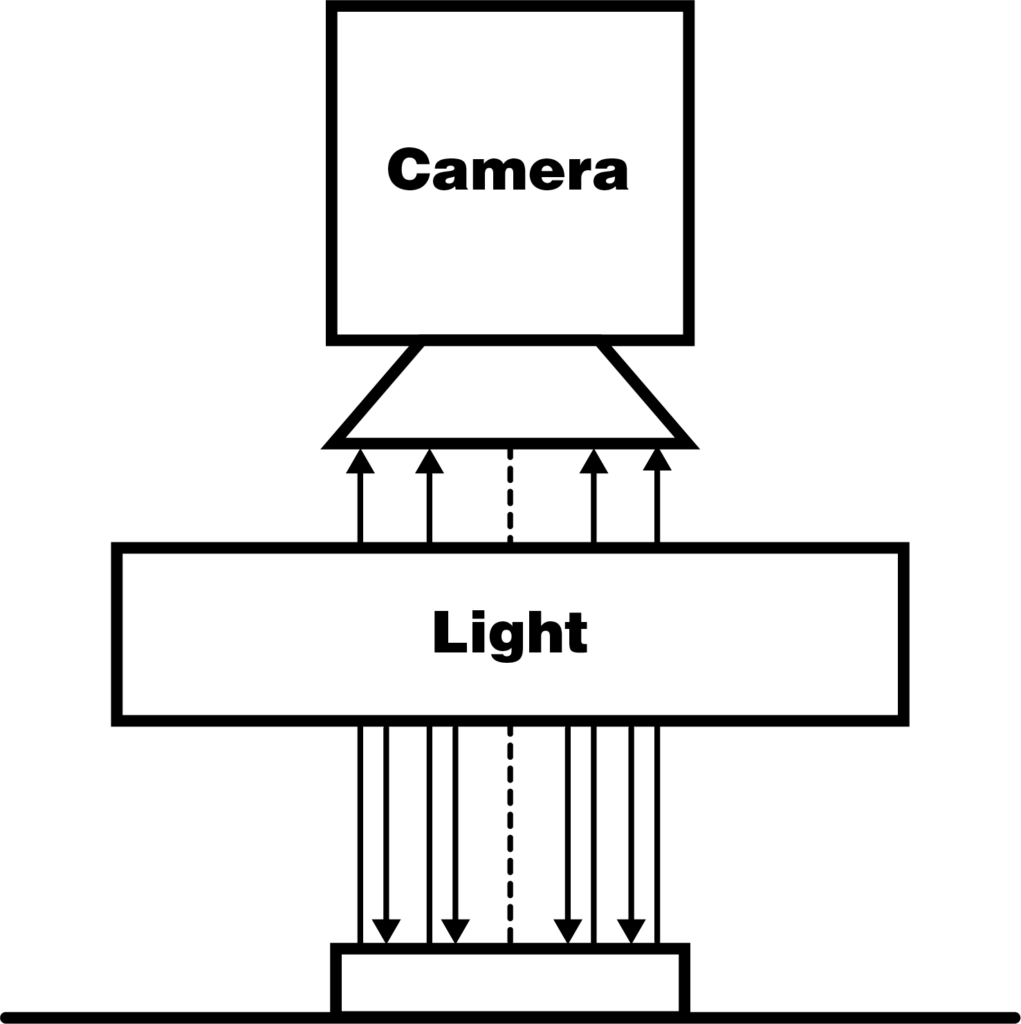
2d camera technology
2D image capture is based on the principle of the human eye – light falls on an object, is reflected and captured by the eye. In our machines, artificial lighting is used to generate light beams that are reflected by the object and captured by the camera. The selection of the appropriate lighting and camera depends on the type of application. The following features can be checked using 2D camera technology:
- Colours and colour variations
- Stains
- Damage and scratches
- Batch mixing
- Surface brilliance and texture
- Burr on the profile of the objects
- Labels
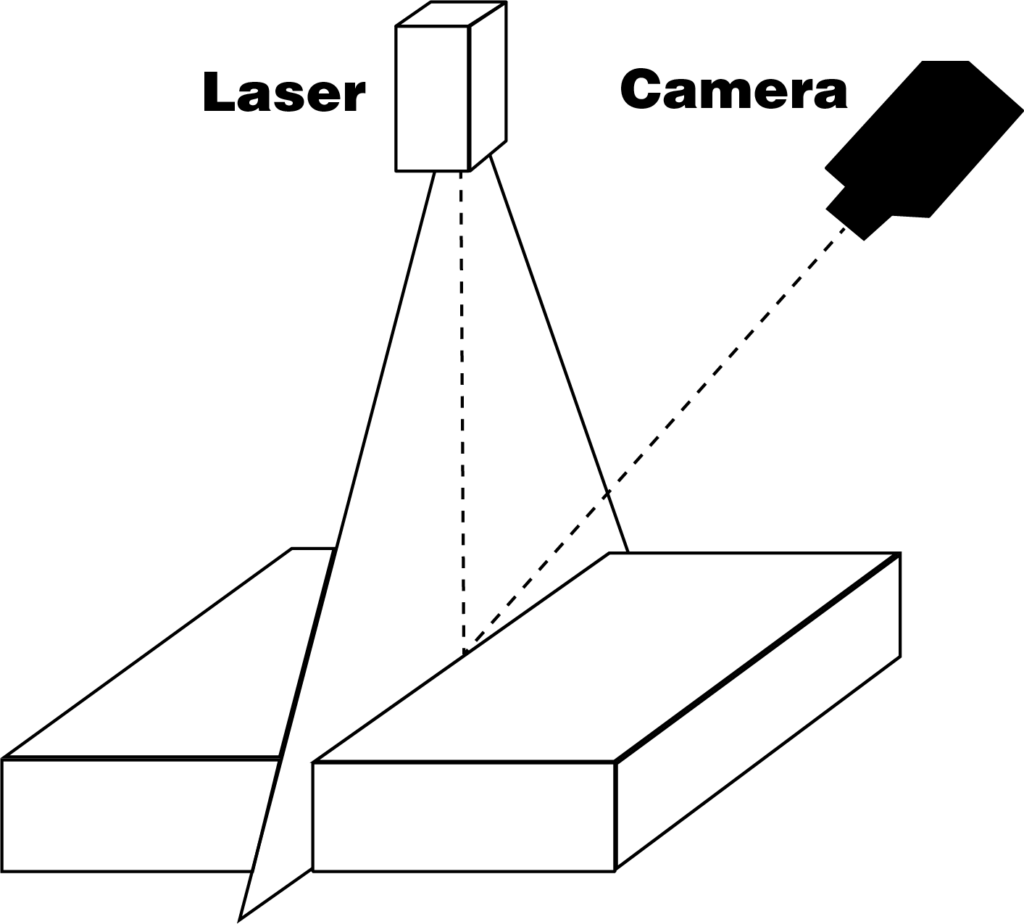
3D camera technology
3D image capture picks up where 2D camera technology reaches its limits, particularly with regard to the depth of field of the images and the ability to detect differences in height. To create a height profile, the component is illuminated with a line laser. The laser beam is reflected and captured by a camera. The illumination of the line laser generates many cross-sectional images. This partial information about the component is assembled by the software to form a complete object.
The following characteristics can be checked using 3D camera technology:
- Geometry and shape
- Deflection of objects
- Damage and scratches
- Batch mixing
- Blockages caused by foreign objects within e.g. boreholes
- Labels
- Embossing and textures
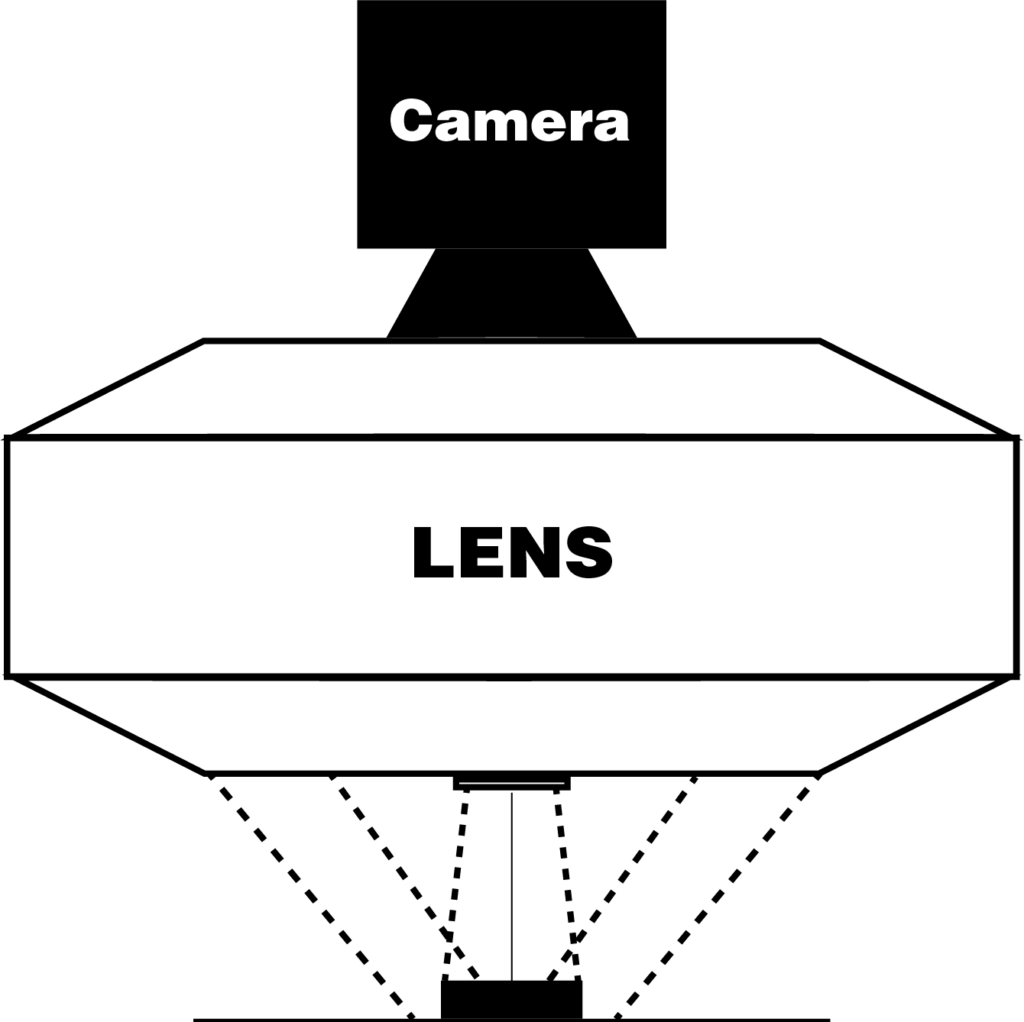
2D camera technology for edge inspection
For geometric reasons, 2D and 3D camera technology only captures the top and bottom of an object, but not the edge surfaces. A special 2D camera in combination with a ring light and a catadioptric lens is used to inspect the edge surfaces.
The following features can be checked using 2D camera technology for edge inspection:
- Damage/scratches
- Batch mixing
- Labelling errors
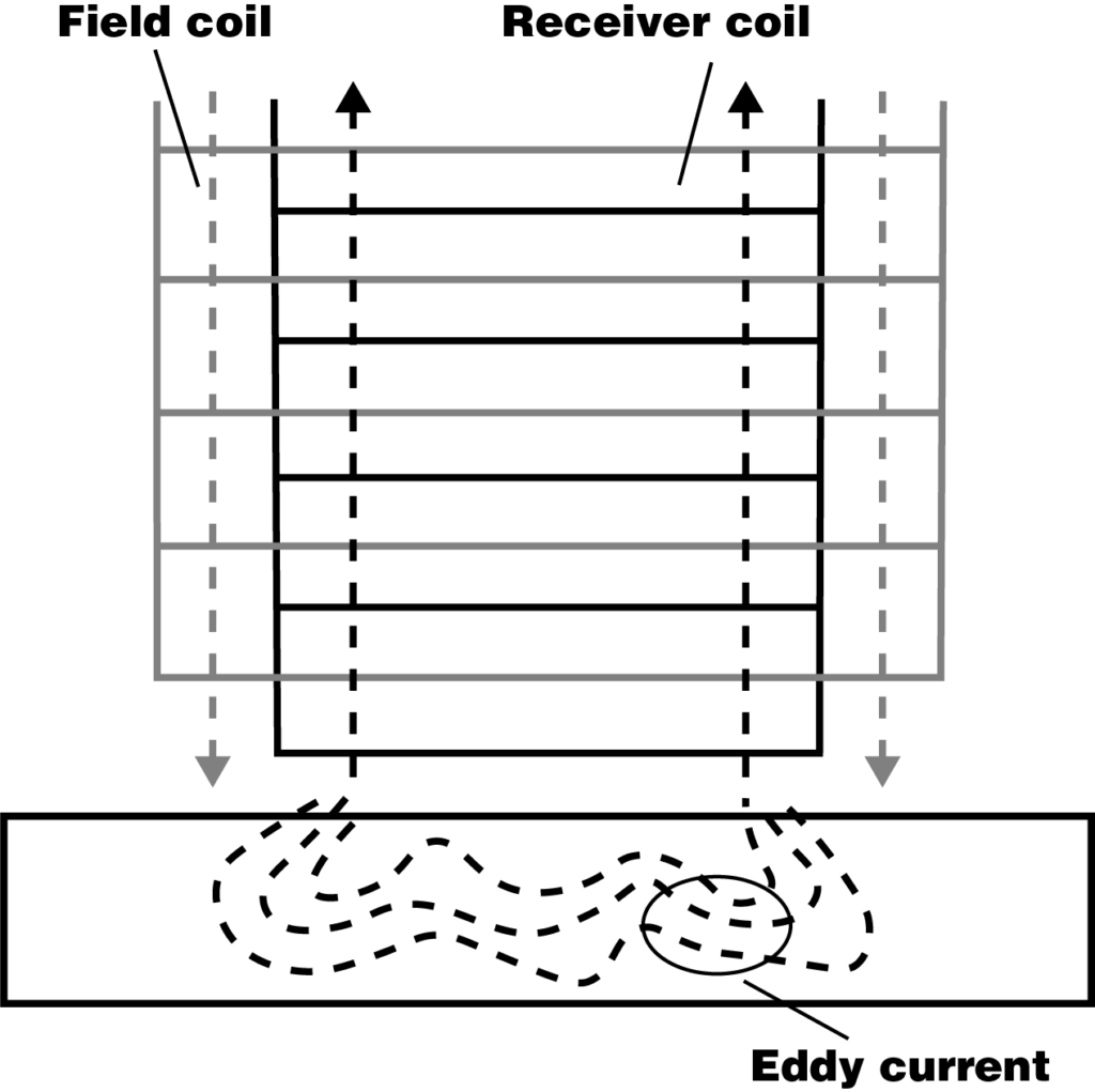
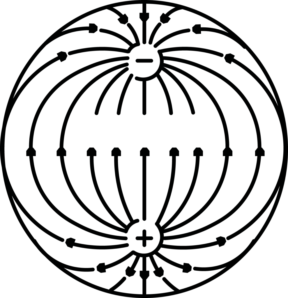
Eddy current measurement
Eddy current measurement is a non-destructive method for testing metallic surfaces. With the aid of high-frequency electromagnetic interactions, different material hardnesses can be detected and analysed both manually and automatically. This method plays a crucial role in quality assurance, as it measures the mechanical resistance of a material to the penetration of another body.
EMS sensors
This measurement principle for checking electromagnetic signatures is now used worldwide in coin-operated machines. Inductive testing of coins or coin blanks provides information about the material composition and/or coating of the coin/blank. The measured values of the individual object are compared with a material database and, depending on the deviation from the references or the deviation defined as acceptable, are rated as good or bad.
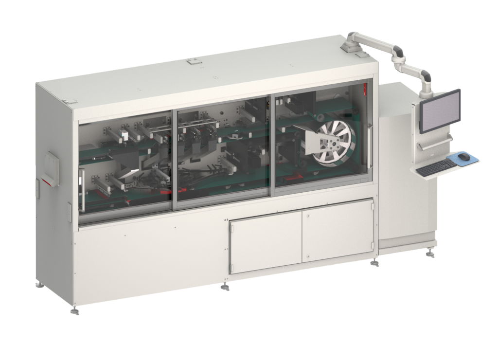
Inspection systems SIT
Our inspection systems check the surfaces of your workpieces according to defined quality standards – reliably, repeatably and precisely. They detect and classify surface defects such as scratches, cracks or contamination. In addition, they enable precise dimensional checks and counting functions – fully automatically and in real time. This provides you with complete documentation of the quality status of your products, which is particularly important in series production or safety-critical applications.
Handling
Handling examples
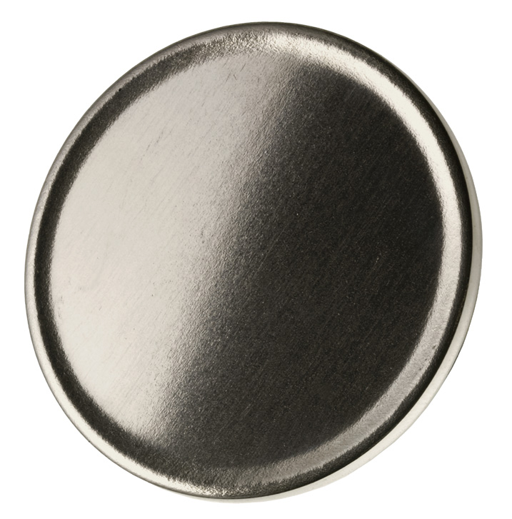
Example 1: Coin Blank
Dimensions:
Diameter 10-35 mm, Thickness 1 – 3.5 mm
Material:
all coin materials
Features:
Stains, color differences, damage, deformation
Tools:
2D and 3D inspection, edge inspection and/or EMS sensor optional
Inspected Sides:
2
Degree of Automation:
high
Speed:
up to 3000 pcs/min at 20 mm diameter

Example 2: Coin/Medal
Dimensions:
Diameter 10-35 mm, Thickness 1 – 3.5 mm
Material:
all coin materials
Features:
Stains, color differences, damage, relief defects, deformation
Tools:
2D and 3D camera technology, optional 2D camera technology for edge inspection and/or EMS sensor
Inspected Sides:
2
Degree of Automation:
high
Speed:
up to 2000 pcs/min at 20 mm diameter

Inspection technology for maximum precision
Our proprietary software platform has been specially developed for flexible customisation to different inspection tasks. It enables differentiated defect classification, the integration of individual inspection parameters and comprehensive statistical analysis of the results. This allows trends to be recognised, process deviations to be identified at an early stage and quality data to be analysed in a targeted manner.
Customised material handling
The workpieces are transported, fed and handled using customised handling systems developed by our own mechanical engineering department. These are optimised to meet the requirements of the inspection technology used – from the cycle time and alignment of the components to seamless integration into existing production lines.
Do you have any questions?
Your contacts for inspection technology


Inspection technology
FAQ
What workpiece sizes can be processed in trough vibrators?
The processable workpiece sizes primarily depend on the selected machine size and the usable internal length of the processing container. Our trough vibrators are specifically designed for long or bulky components that do not fit into circular systems. The available container volume ranges from a compact 40 liters to a generous 1,000 liters for the STV1000 model. With a maximum container length of up to 2,150 mm, even very large-format workpieces can be processed over their entire length without difficulty. By using adjustable dividers, the processing space can also be flexibly adapted for smaller, touch-sensitive components.
What materials can be processed with trough vibrators?
In our trough vibrators, you can reliably process almost all common industrial materials. The spectrum includes various metals such as steel, aluminum, or stainless steel, as well as a wide range of plastics and ceramic materials. An important prerequisite for optimal results is sufficient inherent rigidity of the component, so that the necessary friction between the abrasive media and the workpiece can be generated. We would be pleased to check the suitability of your specific material for processing in the STV series on a case-by-case basis.
What workpiece sizes can be processed in circular vibrators?
The maximum dimensions of workpieces to be processed are primarily determined by the system size and, more specifically, by the width of the processing channel in circular trough vibrators. To ensure uniform and effective surface finishing, the component must be able to move and rotate freely within the abrasive media mass without jamming. For this reason, it is essential to always consider the dimensions of the workpieces in relation to the respective channel geometry and the selected abrasive media size. We would be happy to support you with individual consultation to help you choose the right system for your components.
Which materials can be processed with circular vibratory bowls?
In principle, almost all materials can be processed in our circular vibratory bowls. It makes no difference whether they are metals, plastics, or ceramics. However, a decisive factor for successful processing is a certain rigidity of the material. With very elastic materials, there is a possibility that the required relative movement between the workpiece and the abrasive media may not occur to the necessary extent. We will be happy to examine on a case-by-case basis whether your specific material is suitable for processing in circular vibratory bowls.
What is a centrifugal force system?
A disc centrifugal machine is a vibratory finishing machine in which the workpieces are processed together with the abrasive media in a container, and a rotating disc in the base generates the process movement. This disc sets the mass in a controlled, intensive circular motion, ensuring very uniform processing with high removal rates, even with demanding surfaces and geometries.
Difference to vibration systems: While vibration systems mainly generate movement through oscillations, the disc centrifugal system works with a rotating, ‘pulling’ movement through the rotating disc. This often makes the machining processes faster, more intensive and more precisely controllable – especially when it comes to defined edge rounding, deburring or surface finishing in a short time.
How do alkaline and acidic compounds differ in their effects?
Alkaline compounds are primarily used as cleaners. They are particularly effective against grease, oil and dirt deposits. Acidic compounds, on the other hand, are used for pickling. They remove oxides, rust, scale and other contaminants, preparing the surface specifically for subsequent processing steps. These can include coatings or paint finishes, for example.